
What is MCB ?
A miniature circuit breaker (MCB) is an Electrical Switch that automatically switches off the electrical circuit during an abnormal condition of the network means an overload condition as well as a faulty condition. MCB or Miniature Circuit Breaker is an electromechanical device that protects an electric circuit from an overcurrent. The overcurrent in an electrical circuit may result from short circuit, overload or faulty design.
In short, MCB is a device for overload and short circuit protection. They are used in residential & commercial areas. Just like we spend the time to make a thorough check before buying appliances like washing machines or refrigerators, we must also research about Miniature Circuit Breakers.
Nowadays we use an MCB in a low-voltage electrical network instead of a fuse. The fuse may not sense it but the miniature circuit breaker does it in a more reliable way. MCB is much more sensitive to overcurrent than a fuse.
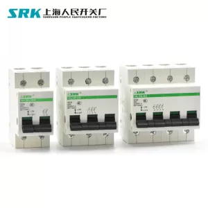
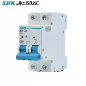
This is what an MCB looks like-
 – Construction, Working, Types &Amp; Trip Curves&Amp; Applications 1")
Construction-
 – Construction, Working, Types &Amp; Trip Curves&Amp; Applications 2")
Incoming Terminal/Outgoing Terminal/Din Rail Holder/Arc Chutes Holder/Arc Chutes/Fixed Contact/Dynamic Contact/Bi-metallic Strip Carrier/Bi-metallic Strip/Latch/Plunger/Solenoid
/Switch
Main contacts: These are the contacts that carry the load current and are connected to the incoming and outgoing wires of the circuit.
Trip Unit: This is the core component of an MCB, which monitors the current flowing through the circuit and trips the breaker in case of an over-current or short-circuit. The trip unit consists of a bimetallic strip, a magnetic actuator, and an operating mechanism.
Terminal: These are the connections for the incoming and outgoing wires.
Housing: The housing is the protective casing that houses the MCB components and provides insulation between live parts and other electrical components.
Trip Indicator: An MCB typically has a visual indicator that shows whether the breaker is in the “on” or “off” position.
Auxiliary contacts: Some MCBs have additional contacts that can be used to switch auxiliary loads or provide signaling functions.
Trip spring: This is the spring mechanism that holds the MCB contacts in the “on” position. When the trip unit operates, the trip spring releases, allowing the contacts to separate and break the circuit.
Working & Operation of MCB
Under normal working conditions, MCB operates as a switch (manual one) to make the circuit ON or OFF. Under overload or short circuit condition, it automatically operates or trips so that current interruption takes place in the load circuit.
The visual indication of this trip can be observed by automatic movement of the operating knob to OFF position. This automatic operation MCB can be obtained in two ways as we have seen in MCB construction; those are magnetic tripping and thermal tripping
Under overload conditions, the current through the bimetal causes it to raise the temperature of it. The heat generated within the bimetal itself is enough to cause deflection due to thermal expansion of metals. This deflection further releases the trip latch and hence contacts get separated.
In some MCBs, the magnetic field generated by the coil causes it to develop pull on bimetals such that deflection activates the tripping mechanism.
Under short circuit or heavy overload conditions, magnetic tripping arrangement comes into the picture. Under normal working conditions, the slug is held in a position by a light spring because the magnetic field generated by the coil is not sufficient to attract the latch.
When a fault current flows, the magnetic field generated by the coil is sufficient to overcome the spring force holding the slug in position. And hence slug moves and then actuate the tripping mechanism.
A combination of both magnetic and thermal tripping mechanisms are implemented in most miniature circuit breakers. In both magnetic and thermal tripping operations, an arc is formed when the contacts start separating. This arc is then forced into arc splitter plates via arc runner.
These arc splitter plates are also called arc chutes where arc is formed into a series of arcs and at the same time energy extracted and cools it. Hence this arrangement achieves the arc extinction.
 – Construction, Working, Types &Amp; Trip Curves&Amp; Applications 3")
Types & Trip Curves
Different types of MCBs used in Electrical Protection Systems
In the context of Miniature Circuit Breakers (MCBs), the terms Type A, Type B, Type C, Type D, Type E, and Type F refer to different levels of protection provided by the device.
- Type A: Type A MCBs are designed to provide protection against over-current. They are suitable for use in circuits where the maximum expected current is known and relatively constant, such as lighting circuits.
- Type B: Type B MCBs are designed to provide protection against over-current and short circuits. They are suitable for use in circuits where the load is variable, such as in motor circuits. Type B devices are generally suitable for domestic applications. They may also be used in light commercial applications where switching surges are low or non-existent.
- Type C: Type C MCBs are designed to provide protection against both over-current and earth fault currents. They are suitable for use in circuits where there is a high risk of earth fault currents, such as in circuits powered by direct current (DC) or in circuits that include sensitive electronic equipment. Type C devices are the normal choice for commercial and industrial applications where fluorescent lighting, motors etc. are in use. These devices are designed to trip at 5-10 times rated current (50-100A for a 10A device).
- Type D: Type D MCBs are designed to provide protection against over-current and earth fault currents, with a higher tripping threshold than Type C MCBs. They are suitable for use in circuits where there is a high risk of earth fault currents, but where the fault current is expected to be higher than what can be protected by Type C MCBs. The Type D devices have more limited applications, normally in industrial use where high inrush currents may be expected. Examples include large battery charging systems, winding motors, transformers, X-ray machines and some types of discharge lighting. Type D devices are designed to trip at 10-20 times (100-200A for a 10A device).
- Type G: Type G MCBs are designed to provide protection against over-current and earth fault currents in residual current devices (RCDs) used in electrical systems.
- Type H: Type H MCBs are designed to provide protection against over-current and earth fault currents in electrical systems that are powered by direct current (DC).
- Type K: Type K MCBs are designed to provide protection against over-current and short circuits in electrical systems with high fault levels.
 – Construction, Working, Types &Amp; Trip Curves&Amp; Applications 4")
Whenever continuous overcurrent flows through MCB, the bimetallic strip is heated and deflects by bending. This deflection of the bi-metallic strip releases a mechanical latch. As this mechanical latch is attached to the operating mechanism, it causes to open the miniature circuit breaker contacts, and the MCB turns off thereby stopping the current to flow in the circuit. To restart the flow of current the MCB must be manually turned ON. This mechanism protects from faults arising due to overcurrent or overload and short circuits.
But during short circuit conditions, the current rises suddenly, causing electromechanical displacement of the plunger associated with a tripping coil or solenoid. The plunger strikes the trip lever causing the immediate release of the latch mechanism consequently opening the circuit breaker contacts. This was a simple explanation of a miniature circuit breaker’s working principle.
An MCB is very simple, easy to use, and is not generally repaired. It is just easier to replace. The trip unit is the main part, responsible for its proper working. There are two main types of trip mechanisms. A bi-metal provides protection against overload current and an electromagnet provides protection against electric short-circuit current.
Types of MCB based on Number of Poles
Another practical way of distinguishing MCBs is by way of the number of poles supported by the circuit breaker. Based on that, the following types exist:
1. Single Pole (SP) MCB
 – Construction, Working, Types &Amp; Trip Curves&Amp; Applications 5")
A single-pole MCB provides switching and protection only for one single phase of a circuit.
2. Double Pole (DP) MCB
 – Construction, Working, Types &Amp; Trip Curves&Amp; Applications 6")
A two Pole MCB provides switching and protection both for a phase and the neutral.
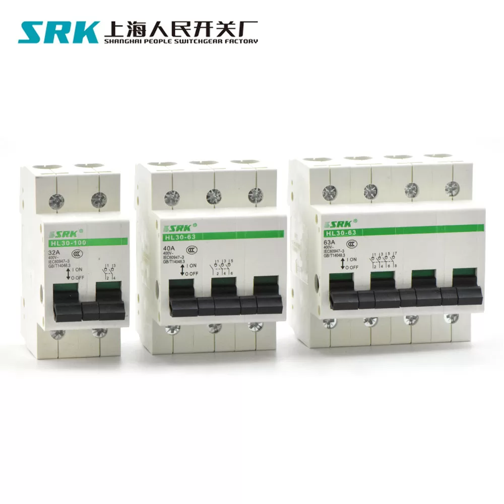
- Triple Pole (TP) MCB
 – Construction, Working, Types &Amp; Trip Curves&Amp; Applications 7")
A triple/three phase miniature circuit breaker provides switching and protection only to three phases of the circuit and not to the neutral.
4. Three Pole with Neutral [TPN (3P+N) MCB]
A TPN MCB has switching and protection to all three phases of the circuit and additionally Neutral is also part of the MCB as a separate pole.
 – Construction, Working, Types &Amp; Trip Curves&Amp; Applications 8")
However, Neutral pole is without any protection and can only be switched.
5. Four Pole (4P) MCB
A 4 pole MCB is similar to TPN but additionally, it also has a protective release for the neutral pole.
 – Construction, Working, Types &Amp; Trip Curves&Amp; Applications 9")
Selection of Right MCB
The decision to use Type B, C or D miniature circuit breakers for final circuit protection in residential, commercial, industrial or public buildings can be based on a few simple rules.
However, an understanding of the differences between these types of devices can help the installer overcome problems of unwanted tripping or make a suitable selection where lines of demarcation are less clearly defined.
It should be stressed that the primary purpose of circuit protection devices such as miniature circuit breakers and fuses is to protect the cable downstream of the device.
The essential distinction between Type B, C or D devices is based on their ability to handle surge currents without tripping. These are, typically, inrush currents associated with fluorescent and other forms of discharge lighting, induction motors, battery charging equipment, etc.
- Type B, C, and D are used for overcurrent protection of cables in accordance with IEC/EN 60898-1
- Type K for the protecting motors and transformers and simultaneous overcurrent protection of cables with overload tripping based on IEC/EN 60947-2
- Type Z for control circuits with high impedances, voltage converter circuits, and semi cable protection and simultaneous overcurrent protection of cables with overload tripping based on IEC/EN 60947-2.
How To Select Rating Of MCB at a Particular Circuit
If the proper rating is not selected on a particular circuit, there will be no proper functions of MCB at overload. Therefore it is very important to select the right rating of MCB which can be easily calculated as under.
Example
Let’s imagine you have 4 Fans, One TV, 4 Tubes, One V.C.D., One Refrigerator & one 1.5 Ton Air Conditioner on a particular circuit.
The current in that circuit will be (4 x 0.40) + (0.55) + (4×0.20) + (0.22) + (1.6) + (11) = 16 AMP.
Therefore, the suitable rating of MCB will be 20 AMP B Series.
For ready reference current of some important appliance is given below to calculating the preferred rating of MCB.
Calculating Power consumption : 1 Unit = Rs. 4.50 = 1000 watt/hours = 1 Kw/hours.
MCB Selection Table
The MCB selection table helps you to choose the right MCB for protecting your circuit.
 – Construction, Working, Types &Amp; Trip Curves&Amp; Applications 10")
 – Construction, Working, Types &Amp; Trip Curves&Amp; Applications 11")
Contact us:
Kani Xie
SHANGHAI PEOPLE SWITCHGEAR FACTORY
E-mail:Kani@srkswitchgear.com
Ph: 0086 13695872200
Wechat/ WhatsApp/skype: +86 13695872200