Low voltage electrical appliance selection principle
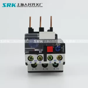
- Selection of thermal relay
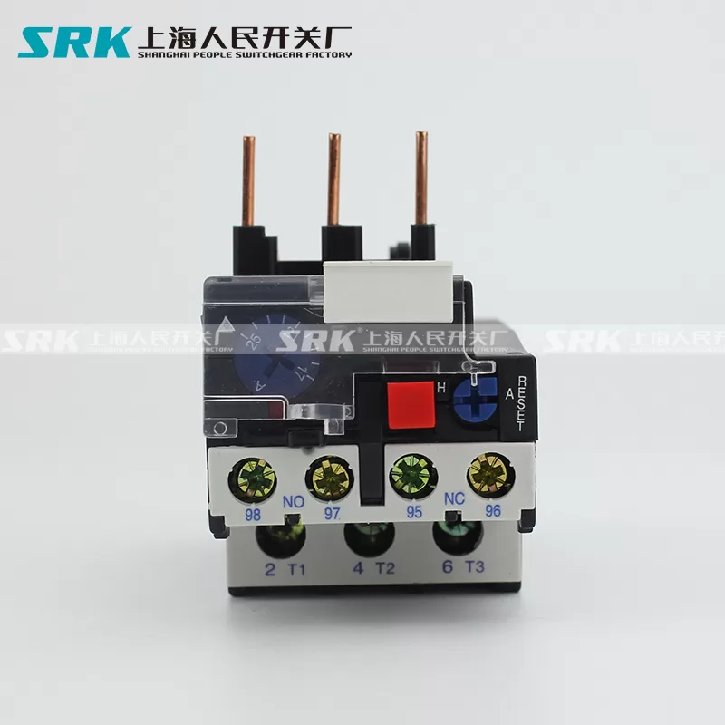
First of all, the trip value of the thermal relay thermal inactive current is 1.05 In, and the operating current is 1.2In, which is designed according to the overload characteristics of the motor. Therefore, when the heat relay is selected, the current adjustment range of the heat relay can meet the rated current of the motor.
Second, according to the motor is light load start or heavy load start to select the heat relay trip extra grade, generally divided into 10A, 10, 20, 30 several grades, respectively corresponding to 7.2In heat relay trip time (under the condition of 20 degrees of ambient temperature). Such as water pump load, for light load start with 10A class. Fan load for heavy start, with 20 grade.
2, plastic shell type circuit breaker - circuit breaker general selection principle
(1) The rated working voltage of the circuit breaker is not less than the rated line voltage.
(2) Rated circuit breaker current ≥ line load current.
(3) The rated short-circuit on-off capacity of the circuit breaker is not less than the maximum short-circuit current that may occur in the line (calculated as effective value).
(4) The single-phase short-circuit current to ground at the end of the line is not less than 1.25 times the instantaneous trip setting current of the circuit breaker.
(5) The rated voltage of the undervoltage trip of the circuit breaker is equal to the rated voltage of the line.
(6) Rated voltage of shunt trip of circuit breaker = voltage of control power supply.
(7) Rated working voltage of electric transmission motor = voltage of control power supply.
(8) Check the allowable connection direction of the circuit breaker. Some types of circuit breakers allow only the up and down line, while others allow the up and down line.
- Selection principle of circuit breaker for distribution
(1) Setting value of circuit breaker long-duration operation current ≤ allowable carrying capacity of conductor. If cables and wires are used, 80% of the allowable carrying capacity of the cables and wires is recommended.
(2) The starting time of the motor whose returnable time of the setting value of the operation current with 3 times the long delay is greater than or equal to the maximum starting current in the line.
(3) Instantaneous current setting value ≥1.1X (Ijx+k1kIedm)
Ijx———— line calculation load current;
k1———— The impact coefficient of motor starting current, generally take k1=1.7-2;
k———— multiple of motor starting current;
Icdm———— Maximum rated current of a motor
- Selection principle of motor protection circuit breaker
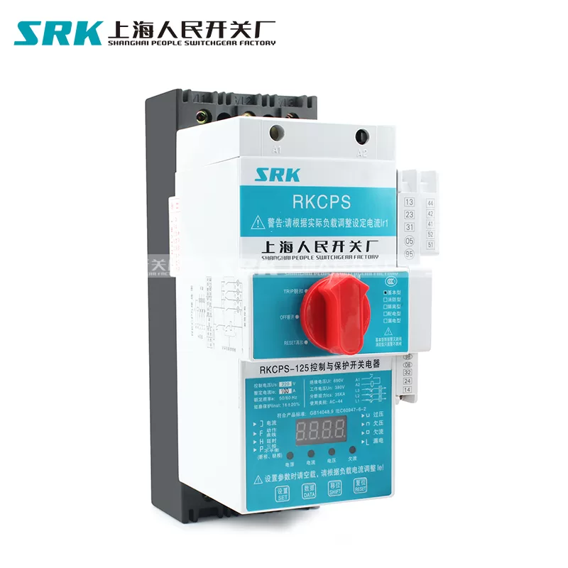
(1) Long delay current setting = rated current of motor
(2) Instantaneous setting current:
For the circuit breaker protecting the cage motor, the instantaneous setting current = (8-15) times the rated current of the motor;
For circuit breakers protecting wound rotor motors, instantaneous setting current = (3-6) times rated motor current.
(3) The returnable time of 6 times long delay current setting value is not less than the actual starting time of the motor. According to the weight of the starting load, the returnable time can be selected as one of the first gear of 1S, 3S, 5S, 8S, 12S and 15S.
3, circuit breaker and fuse coordination principle
(1) If the expected short-circuit current at the installation point is less than the rated breaking capacity of the circuit breaker, the fuse can be used as backup protection, because the rated short-circuit analysis capacity of the fuse is strong. As shown in Figure 1, property 1 of the backup fuse intersects property 2 of the circuit breaker. When the circuit is short, the break time of the fuse is shorter than that of the circuit breaker, which can ensure the safety of the circuit breaker. The junction on the characteristics can be selected at 80% of the rated short-circuit breaking capacity of the circuit breaker.
(2) The fuse should be installed on the power side of the circuit breaker to ensure the safety of use.
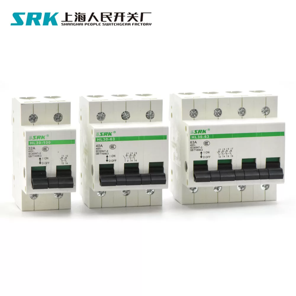
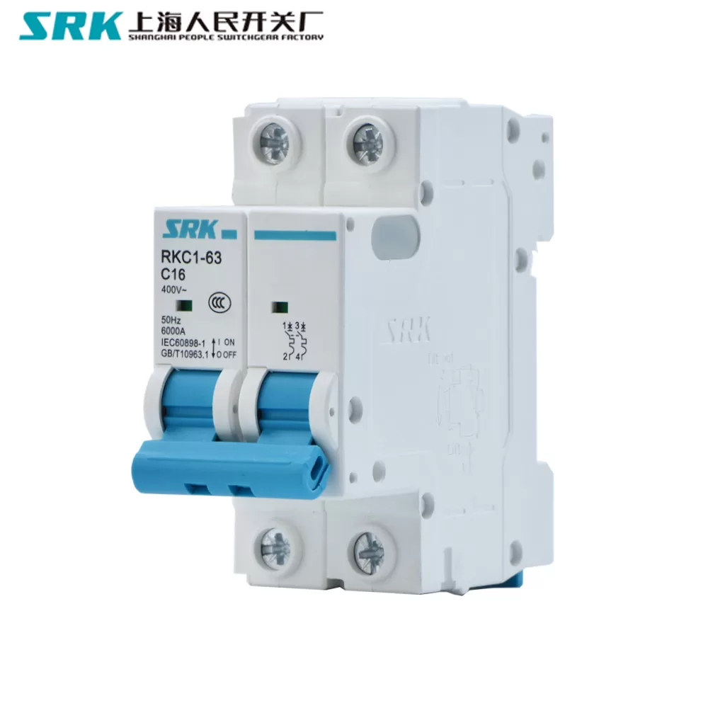
Three, the concept of the number of low-voltage circuit breaker pole I think there is no need to explain to you here, you can go to GB14048.1 "Low-voltage switchgear and control equipment General Provisions". Let me explain to you the number of poles on the circuit breaker. Generally, there are 2, 3 and 4 poles, and the form of 4 poles has four forms: A, B, C and D:
1) A: four without overcurrent trip device, and not with the other three pole on and off;
2) B: four without overcurrent trip, and with the other three poles on and off;
3) C: four poles with over-current release device, and not with the other three poles on and off;
4) D: four poles with over-current release device, and with the other three poles on and off;


